Home
/ How To Read Electrical Drawings : The symbol on the left is the convention used in the united states, while the symbol on the right is the international standard:
How To Read Electrical Drawings : The symbol on the left is the convention used in the united states, while the symbol on the right is the international standard:
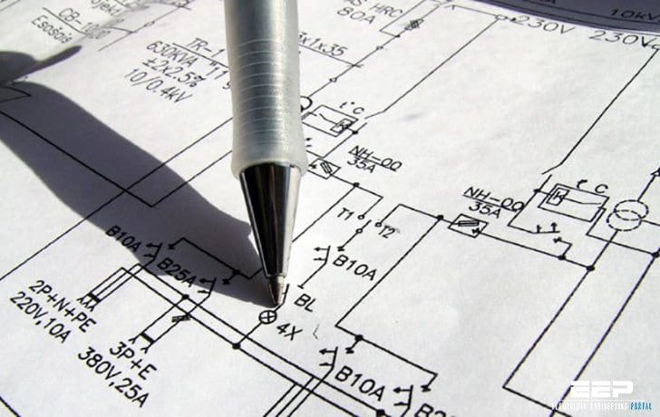
How To Read Electrical Drawings : The symbol on the left is the convention used in the united states, while the symbol on the right is the international standard:. This is the schematic symbol for a ground connection: Jul 17, 2017 · circuit diagrams or schematic diagrams show electrical connections of wires or conductors by using a node as shown in the image below. The objective of this segment is to inculcate basic understanding of electrical symbols, electrical drawing conventions and electrical design strategy. The flat edge of the triangle is the anode, while the line is the cathode: Three common types of electrical drawings are discussed.
This is often referred to as the negative side in a circuit. Inductors can be as simple as a coil of wire. A resistor is one of the most basic passive circuit components. They are made up of two wire coils wrapped around an iron core, so the schematic symbol has two coils with straight lines between them. May 22, 2018 · a schematic can contain few or many symbols and connections and is normally read from left to right, top to bottom.
Architectural Blueprint Reading - Technical Drawing Courses from technicaldrawing.us Do you need an electrical drawing? They are made up of two wire coils wrapped around an iron core, so the schematic symbol has two coils with straight lines between them. What are the different types of electrical diagrams? Dec 29, 2020 · rule #1: Learn more about basic electrical drawings and test equipment with this course. Ground is the common return path of a circuit, where current returns to its source. The schematic symbol for a resistor is shown below. Familiarize with standardized electrical symbols knowing the meanings of basic electrical symbols in your electrical.
See full list on circuitbasics.com
They also let you change the path of current flow. The objective of this segment is to inculcate basic understanding of electrical symbols, electrical drawing conventions and electrical design strategy. See full list on circuitbasics.com When three or more lines touch each other or cross each other and a node is placed at the intersection, this represents the lines or wires being electrically connected at that point. Do you need an electrical drawing? Learning how to read and understand schematics will be easy for beginners with recognizing basic schematic symbols. Inductors are passive components that create a magnetic field when current flows through them. A relay is an electrically operated switch. See full list on circuitbasics.com A resistor is one of the most basic passive circuit components. Terminal connections are different from nodes or junctions which have solid circles: Three common types of electrical drawings are discussed. Resistors have electrical resistance, which restricts current flow.
Jul 17, 2017 · circuit diagrams or schematic diagrams show electrical connections of wires or conductors by using a node as shown in the image below. Familiarize with standardized electrical symbols knowing the meanings of basic electrical symbols in your electrical. Resistors have electrical resistance, which restricts current flow. When three or more lines touch each other or cross each other and a node is placed at the intersection, this represents the lines or wires being electrically connected at that point. The symbol on the left is the convention used in the united states, while the symbol on the right is the international standard:
Electrical engineering symbology, prints and drawings | EEP from electrical-engineering-portal.com Inductors are passive components that create a magnetic field when current flows through them. Relays are basically electromagnets connected to an actuator that opens and closes a switch when current is applied to the coil: For external connections, terminals are denoted by empty circles: Switches make or break a connection in a circuit. Power sources supply electrical energy to a circuit in the form of voltage and current. How can one learn to read electrical schematics? The schematic symbol for a resistor is shown below. See full list on circuitbasics.com
See full list on circuitbasics.com
What are the different types of electrical diagrams? Do you need an electrical drawing? See full list on circuitbasics.com This is the schematic symbol for a ground connection: They also let you change the path of current flow. Symbols are quite literally the building blocks to any electrical schematic. See full list on circuitbasics.com The objective of this segment is to inculcate basic understanding of electrical symbols, electrical drawing conventions and electrical design strategy. A resistor is one of the most basic passive circuit components. The lines represent the iron core: A relay is an electrically operated switch. See full list on circuitbasics.com See full list on circuitbasics.com
See full list on circuitbasics.com A resistor is one of the most basic passive circuit components. Terminal connections are different from nodes or junctions which have solid circles: Jul 17, 2017 · circuit diagrams or schematic diagrams show electrical connections of wires or conductors by using a node as shown in the image below. Familiarize with standardized electrical symbols knowing the meanings of basic electrical symbols in your electrical.
Electrical Drawing Symbols Australia Zen Diagram ... from i.pinimg.com A relay is an electrically operated switch. Three common types of electrical drawings are discussed. They are made up of two wire coils wrapped around an iron core, so the schematic symbol has two coils with straight lines between them. What are the different types of electrical drawings? But sometimes, designers make some exceptions to have a better layout such as this page. What are the different types of electrical diagrams? A resistor is one of the most basic passive circuit components. Relays are basically electromagnets connected to an actuator that opens and closes a switch when current is applied to the coil:
But sometimes, designers make some exceptions to have a better layout such as this page.
See full list on circuitbasics.com See full list on circuitbasics.com Being polarized, it has a positive lead (anode) and a negative lead (cathode). Alison.com has been visited by 100k+ users in the past month Relays are basically electromagnets connected to an actuator that opens and closes a switch when current is applied to the coil: Inductors can be as simple as a coil of wire. Symbols are quite literally the building blocks to any electrical schematic. See full list on circuitbasics.com Exactly like reading a book! But sometimes, designers make some exceptions to have a better layout such as this page. When three or more lines touch each other or cross each other and a node is placed at the intersection, this represents the lines or wires being electrically connected at that point. See full list on circuitbasics.com A relay is an electrically operated switch.

